 Strain is the deformation of a material resulting from applied force, and it is measured by change in length. It can be either tensile or compressive. A strain gage is a device that varies its electrical resistance in proportion to strain. Strain may result from a number of internal or external influences, including pressure, temperature, or structural change. The most commonly used gages are bonded metallic strain gages, which consist of fine wire or foil assembled in a grid pattern. The grid is bonded to the test specimen and detects changes in length that occur when a load is applied. This leads to a change in resistance, which is measured by an electric circuit. Inhomogeneous materials may present numerous complexities in obtaining accurate strain measurements.
Properties of Inhomogeneous Materials
Until recently, the majority of strain measurements were applied to metals such as steel and aluminum alloys. The current trend of replacing metals with polymers and composites has brought about a growing number of reinforced plastics with significantly different mechanical, thermal, and chemical properties. One major difference in the physical properties of metals and polymers is found in the elastic modulus. A composite material with a polymer or plastic matrix may have an elastic modulus of more than twice that of metals, depending on the fiber material and volume of reinforcement. As a result, strain measurements for these inhomogeneous materials are considerably larger than for metals and usually require special strain gage bonding and wiring techniques.
The thermal conductivity of polymer matrix composites can be as much as two orders of magnitude lower than that of metals. When the test specimen and gage undergo deformation, the gage resistance changes in response to strain and generates a calibrated voltage offset. Strain gages with a higher resistance result in less heating for the voltage produced. However, polymer matrix composites do not conduct heat well and may allow heat to accumulate in the gage. This increase in temperature causes an increase in resistance and, subsequently, an error in strain measurement. In some cases, this may require temperature compensation.
Some inhomogeneous materials are hygroscopic and may expand or contract as moisture content changes. These dimensional fluctuations are not differentiated from thermal output and result in false strain measurements. Plastic composite matrices vary significantly in hygroscopic properties. For example, acrylic plastic has a strong tendency to absorb moisture, while polyethylene absorbs practically no moisture. Wood is another inhomogeneous material prone to absorbing moisture. Wood will expand and contract with atmospheric changes. Additionally, the shrinkage that occurs during drying is less in a direction parallel to the grain than in a direction across the grain. This underscores the necessity of proper specimen selection for compensating strain gages as well as providing consistent atmospheric conditions for both the active and compensating gages.
Gage Length for Inhomogeneous Materials
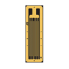
The gage length is defined as the receptive region of the grid. Solder tabs and end loops are excluded from what is regarded as the strain sensing area of the gage due to the comparatively large size of their cross-sectional area and low electrical resistance. Strain gage lengths are typically selected based on the size and shape of the sample and anticipated strain distribution. The gage length also plays an essential role in the accuracy of strain measurements. Strain gages of 0.125 inches or greater usually provide greater stability and measurement range. Additionally, larger gages provide better heat dissipation, since they have a lower wattage per unit of grid area.
Gage length is also an important consideration in strain measurements for inhomogeneous materials such as reinforced plastics and concrete. The length should be large in relation to the size of the inhomogeneities in the sample to provide strain measurements representative of the structure. Measurements of inhomogeneous materials usually seek an average strain rather than the inconsistencies that arise at the peripheries of aggregate and matrix materials.
Gage length is also an important consideration in strain measurements for inhomogeneous materials such as reinforced plastics and concrete. The length should be large in relation to the size of the inhomogeneities in the sample to provide strain measurements representative of the structure. Measurements of inhomogeneous materials usually seek an average strain rather than the inconsistencies that arise at the peripheries of aggregate and matrix materials.
Gage Pattern
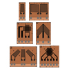
Choosing the right gage pattern is crucial in optimizing strain measurements. The gage pattern designates the configuration of the grid and solder tabs. Grid width may be either narrow or wide, depending upon the application. A narrow grid width minimizes the averaging error for strain gradients aligned vertically to the gage, while wider grids facilitate heat dissipation for specimens that exhibit poor heat transfer properties. The solder tab configuration should concur with the size and position of the installation and allow the connection of lead wires.
Frequently, identical gage patterns are offered with a different resistance; the most common are 120 and 350Ω. The higher resistance gage is most often preferred because it decreases the amount of heat generated and reduces signal noise from lead wires and other sources of resistance changes.
Frequently, identical gage patterns are offered with a different resistance; the most common are 120 and 350Ω. The higher resistance gage is most often preferred because it decreases the amount of heat generated and reduces signal noise from lead wires and other sources of resistance changes.
Adhesives

Strain Gages Designed for Inhomogeneous Materials

The SGD-30/350-LY40 strain gage is made from the same quality materials as the SGD-30/120-LY40. Its 50 mm length improves the accuracy of strain measurements for inhomogeneous materials. The grid is 30 by 3 mm, and the carrier is 36 by 5 mm. Nominal resistance for the SGD-30/350-LY40 is 350Ω. This linear pattern strain gage is designed to measure strain in a single direction.
Conclusion