Anemometer
Introduction to Air Velocity Measurement
An
anemometer is an instrument used to measure the speed or velocity of air (gases) either in a contained flow, such as airflow in a duct, or in unconfined flows, such as atmospheric wind. To determine the air velocity, anemometers detect change in some physical property of the fluid or the effect of the fluid on a mechanical device inserted into the flow.
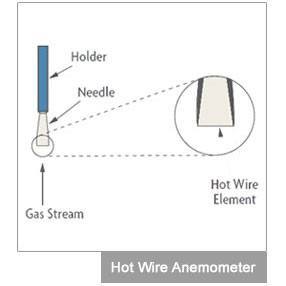
The hot wire anemometer is the most popular kind of constant-temperature devices. It consists of an electrically heated, fine-wire element (0.00016 inch in diameter and 0.05 inch long) supported by needles at its ends. While hot wire are best suited for clean gases at low velocities, venturi meters can also be considered for some liquid (including slurry) flow applications.
OMEGA Engineering offers a wide range of
anemometers in Australia.
Learn more about anemometers
What are anemometers used for?
An anemometer can measure the total velocity magnitude, the velocity magnitude on a horizontal plane, or the velocity component in a
particular direction.
Types of anemometers
There is a wide range of anemometers models for directly measuring wind and air velocity. The four most popular
models are: Vane Anemometers, Thermal Anemometers, Thermal Anemometers with Velocity / Temperature Profiling and
Cup Anemometers. This type of air velocity indicator is usually classified as either constant-temperature, or constant-power anemometers.
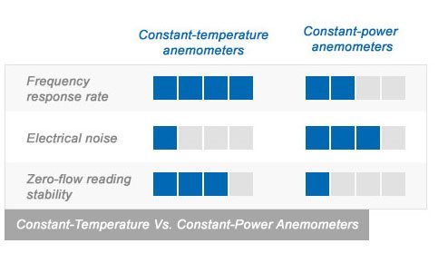
Constant-temperature anemometers are popular because of their high-frequency response, low electronic noise level, immunity
from sensor burnout when airflow suddenly drops, compatibility with hotfilm sensors, and their applicability to liquid or gas
flows.
Constant-power anemometers do not have a feedback system. Temperature is simply proportional to flowrate. They are
less popular because their zero-flow reading is not stable, temperature and velocity response is slow, and temperature compensation is limited.
Anemometer Applications
An anemometer usually measures gas flows that are in turbulent flow conditions. The vane anemometer, thermal anemometer and cup
anemometer (typically used in weather stations) are mostly used to measure the mean velocity, while the hot wire anemometers are
usually used when turbulence characteristics are being measured, such as transverse measurements in a cross-section. The term
"thermal anemometer" is often used to refer to any anemometer using a relationship between heat transfer and velocity to determine velocity.
origin story of anemometers
The term anemometer was derived from the Greek words anemos, “wind,” and metron, “measure.” Mechanical anemometers were
first developed back in the 15th century to measure wind speed.
Anemometers for weather stations
The cup anemometer (used in weather stations) measures the velocity in a plane perpendicular to the axis of its rotation cups.
If the cup anemometer is mounted with the shaft perpendicular to the horizontal, it will measure only the component of the wind
that is parallel to the ground. Other types of anemometer, such as vane anemometers, are used with the tip aligned with the total
velocity vector. Before using an anemometer, it is important to determine how it should be positioned and what component of
the total velocity its measurement represents.
Choose the right anemometer
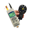
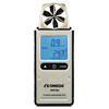
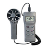
 Vane Anemometers
Forms of rotating mechanical velocity anemometers may be described as belonging to the vane or propeller class. With this style of
anemometer, the axis of rotation must be parallel to the direction of the wind and therefore typically horizontal. In open spaces the
wind varies in direction and the axis has to follow its changes. In cases where the direction of the air motion is always the same,
as in the ventilating shafts of mines and buildings for instance, wind vanes, known as air meters are employed, and give most satisfactory
results. Vane anemometers are available with additional functions such as temperature, humidity and dew point measurements, volumetric
conversion and data logging ability.
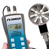
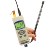
 Thermal Anemometers
Thermal anemometers use a very fine wire (on the order of several micrometers) or element heated up to some temperature above the ambient.
Air flowing past over has a cooling effect. As the electrical resistance of most metals is dependent upon the temperature of the metal
(tungsten is a popular choice for hot wires), a relationship can be obtained between the resistance of the wire and the flow velocity.
Several ways of implementing this exist, and hot-wire devices can be further classified as CCA (Constant-Current Anemometer),
CVA (Constant-Voltage Anemometer) and CTA (Constant-Temperature Anemometer). The voltage output from these anemometers is thus the result
of some sort of circuit within the device trying to maintain the specific variable (current, voltage or temperature) constant. Additionally,
PWM (Pulse Width Modulation) anemometers are also used, wherein the velocity is inferred by the time length of a repeating pulse of current
that brings the wire up to a specified resistance and then stops until a threshold "floor" is reached, at which time the pulse is sent again.
Hot-wire anemometers, while extremely delicate, have extremely high frequency-response and fine spatial resolution compared to other
measurement methods, and as such are almost universally employed for the detailed study of turbulent flows, or any flow in which rapid velocity
fluctuations are of interest. Thermal anemometers are available with additional functions such as temperature measurement, data logging ability.
 Thermal Anemometers with Velocity/Temperature Profiling
Thermal anemometer profiling systems have the smallest available sensor. The sensors measure both velocity and temperature. The multi-point data-logging
system allows the user to profile flow characteristics in the application and analyze the data graphically. These are commonly used in wind tunnels for
circuit board and heat sink analysis.
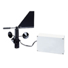
Cup Anemometers
A simple type of anemometer is the cup anemometer. It consisted of three or four hemispherical cups each mounted on one end of horizontal arms, which in
turn were mounted at equal angles to each other on a vertical shaft. The air flow past the cups in any horizontal direction turned the cups in a manner that
was proportional to the wind speed. Therefore, counting the turns of the cups over a set time period produced the average wind speed for a wide range of speeds.
On an anemometer with four cups it is easy to see that since the cups are arranged symmetrically on the end of the arms, the wind always has the hollow of one cup
presented to it and is blowing on the back of the cup on the opposite end of the cross.
When Robinson first designed his anemometer, he wrongly claimed that no matter how big the cups or how long the arms, the cups always moved with one-third of the speed
of the wind. This was apparently confirmed by some early independent experiments, but it was very far from the truth. It was later discovered that the actual relationship
between the speed of the wind and that of the cups, called the anemometer factor, depended on the dimensions of the cups and arms, and may have a value between two and a
little over three. Every single experiment involving an anemometer had to be done all over again.
The three cup anemometer developed by the Canadian John Patterson in 1926 and subsequent cup improvements by Brevoort & Joiner of the USA in 1935 led to a cupwheel
design which was linear and had an error of less than 3% up to 60 mph. Patterson found that each cup produced maximum torque when it was at 45 degrees to the wind flow.
The three cup anemometer also had a more constant torque and responded more quickly to gusts than the four cup anemometer.
The three cup anemometer was further modified by the Australian Derek Weston in 1991 to measure both wind direction and wind speed. Weston added a tag to one cup, which
causes the cup wheel speed to increase and decrease as the tag moves alternately with and against the wind. Wind direction is calculated from these cyclical changes in
cup wheel speed, while wind speed is as usual determined from the average cup wheel speed.
Three cup anemometers are currently used as the industry standard for wind resource assessment studies. The NRG Systems #40C is the most commonly used cup anemometer
for this purpose. For historical reasons, anemometer sizes are measured in crows.
Frquently Asked Questions
Hot Wire or Vane Anemometer?
Sometimes called wind speed or air speed meters, anemometers are generally classified as hot wire or vane. The hot wire anemometer
is best for accurately measuring air flow at very low velocities (eg., under 2000 ft/min). Some models are designed to measure
velocities as high as 15,000 ft/min but still have very accurate measuring capability down to much lower speeds. The vane
anemometer relies in a rotating impeller to sense air velocity. Vane anemometers are the best choice for measuring wind speed.
Many have user selectable units of measure: ft/min, m/s, MPH, km/h and knots to accommodate a wide variety of applications.
A thermoanemometer is any hot wire or vane anemometer having the added feature of air temperature measurement. Hygro-thermometer
anemometers include the features of a thermo anemometer and a humidity sensor giving customer's complete environmental information.
A data logging anemometer is designed to store measurements for later review. Some will download logged air velocity readings
to your computer for review, graphing, and further analysis.
How to use Anemometers in Air Duct Traversing?
Anemometers are widely used for air duct balancing. This is accomplished by placing multiple anemometers in a cross-section of the duct or gas pipe
and manually recording the velocity readings at numerous points. The mass flow rate is obtained by calculating the mean velocity and multiplying this by
the density and by the cross-sectional area measurement of the duct. For cylindrical ducts, the log-linear method of traversing provides the highest
accuracy because it takes into account the effects of friction along the walls of the duct. Because of the number of measurements, air duct traversing
is a time-consuming task. Microprocessor based anemometers are available to automate this procedure.
Because of the small size and fragility of the wire, hot-wire anemometers are susceptible to dirt build-up and breakage. A positive consequence
of their small mass is fast speed of response. They are widely used in HVAC and ventilation applications. Larger and more rugged anemometers are also available for
more demanding industrial applications. To ensure the proper formation of the velocity profile, a straight duct section is usually provided upstream
of the anemometer station (usually 10 diameters long). A conditioning nozzle is used to eliminate boundary layer effects. If there is no room for the
straight pipe section, a honeycomb flow straightener can be incorporated into the sensor assembly.
Shop for Anemometers in Australia
The OMEGA Engineering Singapore office handles all inquiries and orders for Australia. We have Application Engineers and Sale Support Staff ready to assist you with your technical questions, quotations and orders. A one-stop source for process measurement and control, OMEGA provides support through web chat, e-mail and telephone. View our
contact page to call or email us.
Anemometer | Related Products
↓ View this page in another language or region ↓

 Anemômetros
 Anemómetros
 Anemómetros
 Anemometer
 Anemometer
 Anémomètre
 Anemometern
 Anemometro
 Anemometer
 Anemómetro
 Anemometer
 Anemometer
 风速计
风速计 Anemometer
 풍속계
풍속계 Anemometer
 Anemometer
 Anemometer
 Anemometer
 Anemometer